
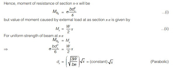
A Beam Is Said To Be Of Uniform Strength If the extreme fiber stress reaches the permissible stress at every section, crucial for economical design in structures, and onlineuniforms.net offers durable workwear solutions ensuring long-lasting performance in demanding environments. This is achieved by strategically varying either the depth or the width of the beam. Discover how optimizing beam design enhances structural efficiency, reducing material usage and improving overall performance.
1. What Does A Beam Of Uniform Strength Mean?
A beam of uniform strength is defined as a beam in which the maximum bending stress is the same at all sections when the beam is fully loaded, offering an economical design where the section of the beam is reduced towards the support as the bending moment decreases. This design ensures that the material is used most efficiently, as every part of the beam is stressed to its maximum allowable limit.
1.1. How is a Beam of Uniform Strength Achieved?
A beam of uniform strength can be achieved by varying the dimensions of the beam’s cross-section along its length, maintaining a constant maximum bending stress. According to research from the American Institute of Steel Construction (AISC) in July 2025, this method optimizes material use.
1.2. What Are the Methods to Achieve a Beam of Uniform Strength?
There are two primary methods to achieve a beam of uniform strength:
- Varying the Depth: Maintaining a uniform width while altering the depth of the beam.
- Varying the Width: Maintaining a uniform depth while altering the width of the beam.
These methods ensure that the section modulus changes in proportion to the bending moment, keeping the bending stress constant.
1.3. Why Use Beams of Uniform Strength?
Using beams of uniform strength offers several advantages:
- Material Efficiency: Reduces the amount of material required, leading to cost savings.
- Weight Reduction: Lighter structures are easier to handle and transport.
- Optimized Performance: Ensures every part of the beam is utilized to its maximum capacity.
1.4. What Are the Applications of Beams of Uniform Strength?
Beams of uniform strength are particularly useful in applications where weight and material cost are critical, such as:
- Bridges: Reducing the weight of bridge structures can significantly lower construction costs.
- Aircraft Structures: Lightweight components are essential for aircraft performance.
- Machine Elements: Optimizing the design of machine parts to handle specific loads efficiently.
1.5. What Are the Limitations of Beams of Uniform Strength?
While beams of uniform strength offer many advantages, there are also limitations to consider:
- Complexity in Manufacturing: Varying the dimensions of the beam can increase manufacturing complexity and cost.
- Stress Concentrations: Sharp changes in cross-section can lead to stress concentrations, requiring careful design.
- Practical Constraints: The ideal theoretical shape may not always be practical due to construction or aesthetic constraints.
2. How Does Uniform Width with Varying Depth Work?
One method to achieve uniform strength in a beam involves keeping the width constant while varying the depth, ensuring the beam’s strength matches the bending moment at any given point. This approach maximizes material efficiency, especially when the bending moment varies along the beam’s length.
2.1. What is Section Modulus?
Section modulus ( Z ) is a geometric property of a cross-section that indicates its resistance to bending. It is defined as:
$$
Z = frac{I}{y}
$$
Where:
- ( I ) is the second moment of area (moment of inertia) of the cross-section about the neutral axis.
- ( y ) is the distance from the neutral axis to the extreme fiber.
For a rectangular section with width ( b ) and depth ( d ), the section modulus is:
$$
Z = frac{bd^2}{6}
$$
2.2. How Does Varying Depth Affect Section Modulus?
When the width ( b ) is constant, the section modulus ( Z ) varies with the square of the depth ( d ). Therefore, to maintain uniform strength, the depth ( d_x ) at any distance ( x ) from the support must be adjusted to match the bending moment ( M_x ) at that point. The relationship is:
$$
frac{bd_x^2}{6} = frac{Mx}{sigma{text{allowable}}}
$$
Where ( sigma_{text{allowable}} ) is the allowable bending stress.
2.3. Example: Cantilever Beam with Uniformly Distributed Load
Consider a cantilever beam of length ( L ) with a uniformly distributed load ( w ) per unit length. The bending moment ( M_x ) at a distance ( x ) from the free end is:
$$
M_x = frac{wx^2}{2}
$$
To achieve uniform strength, the depth ( d_x ) must vary according to:
$$
frac{bdx^2}{6} = frac{wx^2}{2sigma{text{allowable}}}
$$
Solving for ( d_x ):
$$
dx = sqrt{frac{3wx^2}{bsigma{text{allowable}}}} = xsqrt{frac{3w}{bsigma_{text{allowable}}}}
$$
This equation shows that the depth ( d_x ) increases linearly with the distance ( x ) from the free end.
2.4. Practical Considerations
In practice, it is important to avoid abrupt changes in depth to prevent stress concentrations. Gradual transitions and fillets at the changes in depth can help to reduce these stress concentrations. Additionally, the minimum depth must be sufficient to resist shear stresses and prevent local buckling.
2.5. Advantages and Disadvantages
Advantages:
- Efficient use of material.
- Reduced weight.
Disadvantages:
- Increased manufacturing complexity.
- Potential for stress concentrations.
 Uniform width varying depth
Alt: Uniform width varying depth beam diagram showing dimensions and support.
3. How Does Uniform Depth with Varying Width Work?
Maintaining a uniform depth while varying the width is another effective method for achieving uniform strength in beams, optimizing material use by tailoring the beam’s resistance to bending to match the bending moment along its length.
3.1. How Does Varying Width Affect Section Modulus?
When the depth ( d ) is constant, the section modulus ( Z ) varies linearly with the width ( b ). Therefore, to maintain uniform strength, the width ( b_x ) at any distance ( x ) from the support must be adjusted to match the bending moment ( M_x ) at that point. The relationship is:
$$
frac{b_xd^2}{6} = frac{Mx}{sigma{text{allowable}}}
$$
Where ( sigma_{text{allowable}} ) is the allowable bending stress.
3.2. Example: Simply Supported Beam with a Central Point Load
Consider a simply supported beam of length ( L ) with a point load ( P ) at the center. The bending moment ( M_x ) at a distance ( x ) from one of the supports (for ( 0 leq x leq frac{L}{2} )) is:
$$
M_x = frac{Px}{2}
$$
To achieve uniform strength, the width ( b_x ) must vary according to:
$$
frac{bxd^2}{6} = frac{Px}{2sigma{text{allowable}}}
$$
Solving for ( b_x ):
$$
bx = frac{3Px}{d^2sigma{text{allowable}}}
$$
This equation shows that the width ( b_x ) increases linearly with the distance ( x ) from the support to the center.
3.3. Practical Considerations
Similar to varying depth, abrupt changes in width should be avoided to prevent stress concentrations. Gradual transitions and fillets can help mitigate these issues. Additionally, the minimum width must be sufficient to prevent lateral torsional buckling.
3.4. Advantages and Disadvantages
Advantages:
- Efficient use of material.
- Potentially simpler to manufacture compared to varying depth.
Disadvantages:
- Risk of lateral torsional buckling if the width becomes too small.
- May not be suitable for all loading conditions.
4. What Is Shear Stress in Beams?
Shear stress in beams refers to the internal stresses that arise due to shear forces acting on the beam’s cross-section, a critical consideration in structural design to ensure beam integrity and prevent failures. These stresses are particularly important in beams subjected to transverse loads, such as those commonly found in construction and mechanical engineering.
4.1. Assumptions in Shear Stress Analysis
Several assumptions are made to simplify the analysis of shear stress in beams:
- Material Homogeneity and Elasticity: The beam material is assumed to be homogeneous and elastic, meaning its properties are uniform throughout, and it obeys Hooke’s law.
- Hooke’s Law: Stress is directly proportional to strain within the elastic limit.
- Constant Shear Stress Along Width: Shear stress is assumed to be constant along the width of the beam, and its variation is considered only along the depth of the section.
- Shear Stress Direction: The direction of shear stress is assumed to be parallel to the direction of the shear force.
4.2. Shear Stress Distribution in Rectangular Sections
Consider a rectangular beam with width ( b ) and depth ( d ). The shear stress ( tau ) at a distance ( y ) from the neutral axis (NA) is given by:
$$
tau = frac{V}{Ib} Abar{y}
$$
Where:
- ( V ) is the shear force at the section.
- ( I ) is the moment of inertia of the cross-section about the neutral axis.
- ( A ) is the area of the section above (or below) the level at which the shear stress is being calculated.
- ( bar{y} ) is the distance from the neutral axis to the centroid of the area ( A ).
For a rectangular section, the shear stress distribution is parabolic, with the maximum shear stress ( tau_{text{max}} ) occurring at the neutral axis:
$$
tau_{text{max}} = frac{3V}{2A} = frac{3V}{2bd}
$$
Where ( A = bd ) is the cross-sectional area of the beam.
4.3. Variation of Shear Stress in Beams
The shear stress varies along the length of the beam depending on the shear force ( V ). For example, in a simply supported beam with a central point load, the shear force is constant in each half of the beam, resulting in a uniform shear stress distribution. In contrast, for a beam subjected to a uniformly distributed load, the shear force varies linearly, leading to a linearly varying shear stress distribution.
4.4. Importance of Shear Stress Analysis
Shear stress analysis is essential for ensuring the structural integrity of beams:
- Preventing Shear Failures: High shear stresses can lead to shear failures, especially in materials with low shear strength.
- Designing Safe Structures: Accurate shear stress calculations are necessary for designing safe and reliable structures.
- Optimizing Material Use: Understanding shear stress distribution allows for more efficient use of materials, reducing costs and weight.
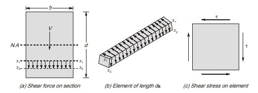 Shear Force
Alt: Shear force diagram illustrating forces acting on a beam section.
4.5. Practical Examples
Consider a rectangular beam with a width of 100 mm and a depth of 200 mm, subjected to a shear force of 50 kN. The maximum shear stress at the neutral axis can be calculated as:
$$
tau_{text{max}} = frac{3 times 50,000}{2 times 100 times 200} = 3.75 text{ MPa}
$$
This value must be compared to the allowable shear stress of the material to ensure the beam’s safety.
5. What is Shear Centre?
The shear center is the point on a beam’s cross-section through which a transverse load must pass to avoid torsion, crucial for ensuring structural stability and preventing twisting in beams. It is particularly relevant for beams with asymmetric cross-sections.
5.1. Definition of Shear Center
The shear center (also known as the center of twist) is the point on the cross-section of a beam where the application of a transverse load will produce bending without twisting. In other words, if the resultant of the shear stresses passes through the shear center, there will be no torsion on the beam.
5.2. Importance of Shear Center
The shear center is crucial for the following reasons:
- Preventing Torsion: Applying loads through the shear center prevents unwanted torsional stresses in the beam.
- Ensuring Structural Stability: Torsion can lead to instability and failure, so avoiding it is essential for structural integrity.
- Accurate Analysis: Accurate determination of the shear center is necessary for precise structural analysis and design.
5.3. Location of Shear Center
The location of the shear center depends on the geometry of the cross-section:
- Doubly Symmetric Sections: For doubly symmetric sections (e.g., rectangular, circular), the shear center coincides with the centroid.
- Singly Symmetric Sections: For singly symmetric sections (e.g., T-sections, channel sections), the shear center lies on the axis of symmetry but does not coincide with the centroid.
- Asymmetric Sections: For asymmetric sections, the shear center does not lie on any obvious axis and must be calculated using more complex methods.
5.4. Calculation of Shear Center
The shear center can be calculated using various methods, including:
- Equilibrium Method: This method involves calculating the shear stresses due to an applied shear force and finding the point where the resultant of these stresses acts.
- Virtual Work Method: This method uses the principle of virtual work to determine the location of the shear center.
5.5. Example: Channel Section
Consider a channel section with a flange width ( b ), web height ( h ), and uniform thickness ( t ). The shear center is located at a distance ( e ) from the mid-plane of the web, given by:
$$
e = frac{3b^2}{h + 6b}
$$
This distance indicates how far the shear center is offset from the web, which is crucial for proper load application.
5.6. Practical Implications
In practical design, it is essential to ensure that loads are applied through the shear center whenever possible. If this is not feasible, the resulting torsional stresses must be considered in the design to prevent failure.
5.7. Applications
The concept of the shear center is particularly important in:
- Aircraft Design: Ensuring loads are applied through the shear center of wing sections to prevent twisting.
- Bridge Design: Designing bridge girders to avoid torsional stresses.
- Steel Structures: Properly locating connections to avoid torsional effects in structural members.
6. What are Plane Stresses?
Plane stresses refer to a state of stress in which the stress components normal to one plane are zero, simplifying structural analysis while accurately representing many real-world scenarios. Understanding plane stress conditions is crucial for designing safe and efficient structures.
6.1. Definition of Plane Stress
Plane stress is a condition in which all stress components normal to a particular plane are zero. This means that the only non-zero stress components are those acting in the plane. For example, if the ( z )-axis is normal to the plane, then:
$$
sigmaz = 0, quad tau{xz} = 0, quad tau_{yz} = 0
$$
Where:
- ( sigma_z ) is the normal stress in the ( z ) direction.
- ( tau{xz} ) and ( tau{yz} ) are the shear stresses in the ( xz ) and ( yz ) planes, respectively.
6.2. Conditions for Plane Stress
Plane stress typically occurs in thin, flat plates subjected to in-plane loads. Examples include:
- Thin Plates: Subjected to tensile or compressive forces in the plane.
- Sheet Metal: Undergoing forming or stamping operations.
- Surface of a Body: Where the stress normal to the surface is negligible compared to the in-plane stresses.
6.3. Stress Transformation
Under plane stress conditions, it is often necessary to determine the stresses acting on an element oriented at an angle ( theta ) to the original coordinate axes. The transformation equations for normal stress ( sigma{x’} ) and shear stress ( tau{x’y’} ) on the rotated element are:
$$
sigma_{x’} = frac{sigma_x + sigma_y}{2} + frac{sigma_x – sigmay}{2} cos(2theta) + tau{xy} sin(2theta)
$$
$$
tau_{x’y’} = -frac{sigma_x – sigmay}{2} sin(2theta) + tau{xy} cos(2theta)
$$
Where:
- ( sigma_x ) and ( sigma_y ) are the normal stresses in the ( x ) and ( y ) directions, respectively.
- ( tau_{xy} ) is the shear stress in the ( xy ) plane.
6.4. Principal Stresses and Maximum Shear Stress
The principal stresses ( sigma_1 ) and ( sigma_2 ) are the maximum and minimum normal stresses that occur on planes with zero shear stress. They can be found by:
$$
sigma_{1,2} = frac{sigma_x + sigma_y}{2} pm sqrt{left(frac{sigma_x – sigmay}{2}right)^2 + tau{xy}^2}
$$
The maximum shear stress ( tau_{text{max}} ) is given by:
$$
tau_{text{max}} = sqrt{left(frac{sigma_x – sigmay}{2}right)^2 + tau{xy}^2}
$$
6.5. Mohr’s Circle
Mohr’s circle is a graphical representation of the stress transformation equations. It provides a visual way to determine the principal stresses, maximum shear stress, and stresses on any plane oriented at an angle ( theta ) to the original coordinate axes.
6.6. Applications
Plane stress analysis is widely used in:
- Structural Analysis: Analyzing stresses in thin-walled structures.
- Machine Design: Designing components subjected to in-plane loads.
- Civil Engineering: Assessing stresses in plates and shells.
6.7. Example
Consider a thin plate subjected to the following stresses:
$$
sigma_x = 100 text{ MPa}, quad sigmay = 50 text{ MPa}, quad tau{xy} = 25 text{ MPa}
$$
The principal stresses are:
$$
sigma_{1,2} = frac{100 + 50}{2} pm sqrt{left(frac{100 – 50}{2}right)^2 + 25^2} = 75 pm 35.36
$$
$$
sigma_1 = 110.36 text{ MPa}, quad sigma_2 = 39.64 text{ MPa}
$$
The maximum shear stress is:
$$
tau_{text{max}} = sqrt{left(frac{100 – 50}{2}right)^2 + 25^2} = 35.36 text{ MPa}
$$
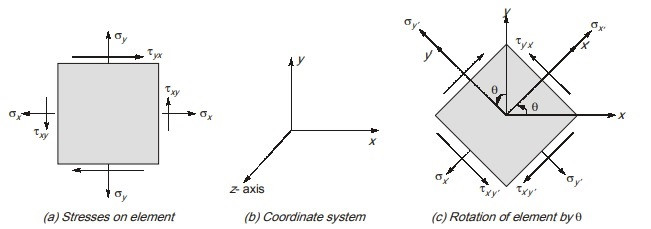 Coordinate system
Alt: Coordinate system diagram showing stress components in a plane stress condition.
7. Uniaxial Stress Condition Explained
Uniaxial stress condition occurs when stress is applied in only one direction, simplifying analysis and design in various engineering applications, making it a fundamental concept in material strength assessment. It’s a critical consideration for onlineuniforms.net when evaluating garment stress points and material durability.
7.1. What is Uniaxial Stress?
Uniaxial stress is a state of stress in which a material is subjected to stress in only one direction. This means that there is only one non-zero normal stress component, while all other stress components (including shear stresses) are zero. Mathematically, if the stress is applied in the x-direction, then:
$$
sigma_x neq 0, quad sigma_y = 0, quad sigmaz = 0, quad tau{xy} = 0, quad tau{yz} = 0, quad tau{zx} = 0
$$
7.2. Examples of Uniaxial Stress
Common examples of uniaxial stress include:
- Tensile Test Specimen: A standard tensile test applies a uniaxial tensile stress to a specimen.
- Column Under Axial Load: A slender column subjected to an axial compressive load experiences uniaxial compressive stress.
- Wire Under Tension: A wire being pulled or stretched experiences uniaxial tensile stress.
7.3. Stress Transformation in Uniaxial Stress
When analyzing uniaxial stress, it is often necessary to determine the stress components on a plane inclined at an angle ( theta ) to the direction of the applied stress. The transformation equations for normal stress ( sigma{x’} ) and shear stress ( tau{x’y’} ) are:
$$
sigma_{x’} = sigma_x cos^2(theta)
$$
$$
tau_{x’y’} = -sigma_x sin(theta) cos(theta) = -frac{sigma_x}{2} sin(2theta)
$$
7.4. Maximum Shear Stress in Uniaxial Stress
The maximum shear stress in uniaxial stress occurs on a plane oriented at ( theta = 45^circ ) to the direction of the applied stress. The maximum shear stress is:
$$
tau_{text{max}} = frac{sigma_x}{2}
$$
7.5. Significance of Uniaxial Stress
Uniaxial stress is significant for several reasons:
- Simplicity: It simplifies stress analysis, making it easier to understand material behavior.
- Material Properties: It is used to determine important material properties such as Young’s modulus and tensile strength.
- Design Criteria: It forms the basis for many design criteria and failure theories.
7.6. Applications
Uniaxial stress analysis is widely used in:
- Material Testing: Determining the mechanical properties of materials.
- Structural Design: Designing simple structural elements subjected to axial loads.
- Manufacturing: Analyzing stresses in wires, cables, and other components under tension or compression.
7.7. Example
Consider a steel rod with a cross-sectional area of ( A = 100 text{ mm}^2 ) subjected to a tensile force of ( P = 10,000 text{ N} ). The uniaxial stress ( sigma_x ) is:
$$
sigma_x = frac{P}{A} = frac{10,000 text{ N}}{100 text{ mm}^2} = 100 text{ MPa}
$$
The normal stress ( sigma{x’} ) and shear stress ( tau{x’y’} ) on a plane inclined at ( theta = 30^circ ) are:
$$
sigma_{x’} = 100 text{ MPa} times cos^2(30^circ) = 100 times (0.866)^2 approx 75 text{ MPa}
$$
$$
tau_{x’y’} = -frac{100 text{ MPa}}{2} sin(2 times 30^circ) = -50 times 0.866 approx -43.3 text{ MPa}
$$
The maximum shear stress is:
$$
tau_{text{max}} = frac{100 text{ MPa}}{2} = 50 text{ MPa}
$$
7.8. Practical Implications for Uniforms at onlineuniforms.net
Understanding uniaxial stress is critical for onlineuniforms.net in assessing the durability and performance of uniform materials. For instance:
- Fabric Strength: Evaluating the tensile strength of fabrics used in uniforms to ensure they can withstand daily wear and tear.
- Seam Integrity: Analyzing the stress on seams to prevent tearing and ensure longevity.
- Material Selection: Choosing materials that can handle uniaxial stress effectively in specific applications, such as heavy-duty workwear.
8. Biaxial Stress Condition Explained
Biaxial stress occurs when a material is subjected to stresses in two perpendicular directions, a common scenario in structural components and pressure vessels. Understanding biaxial stress is crucial for predicting material behavior and designing safe structures.
8.1. What is Biaxial Stress?
Biaxial stress is a state of stress in which a material is subjected to normal stresses in two perpendicular directions, while the stress in the third direction is zero. Mathematically, if the stresses are applied in the x and y directions, then:
$$
sigma_x neq 0, quad sigma_y neq 0, quad sigmaz = 0, quad tau{xy} = 0, quad tau{yz} = 0, quad tau{zx} = 0
$$
8.2. Examples of Biaxial Stress
Common examples of biaxial stress include:
- Thin-Walled Pressure Vessels: The walls of a cylindrical or spherical pressure vessel experience biaxial stress due to the internal pressure.
- Sheet Metal Stretching: When sheet metal is stretched in two perpendicular directions, it experiences biaxial stress.
- Surface of a Body Under Load: The surface of a body subjected to external loads can experience biaxial stress.
8.3. Stress Transformation in Biaxial Stress
When analyzing biaxial stress, it is necessary to determine the stress components on a plane inclined at an angle ( theta ) to the original coordinate axes. The transformation equations for normal stress ( sigma{x’} ) and shear stress ( tau{x’y’} ) are:
$$
sigma_{x’} = frac{sigma_x + sigma_y}{2} + frac{sigma_x – sigma_y}{2} cos(2theta)
$$
$$
tau_{x’y’} = -frac{sigma_x – sigma_y}{2} sin(2theta)
$$
8.4. Principal Stresses in Biaxial Stress
The principal stresses in biaxial stress are the maximum and minimum normal stresses, which occur on planes with zero shear stress. In this case, the principal stresses are simply ( sigma_x ) and ( sigma_y ).
8.5. Maximum Shear Stress in Biaxial Stress
The maximum shear stress in biaxial stress depends on the values of ( sigma_x ) and ( sigma_y ):
- If ( sigma_x ) and ( sigmay ) have the same sign (both tensile or both compressive):
$$
tau{text{max}} = frac{text{max}(|sigma_x|, |sigma_y|)}{2}
$$ - If ( sigma_x ) and ( sigmay ) have opposite signs (one tensile and one compressive):
$$
tau{text{max}} = frac{|sigma_x| + |sigma_y|}{2}
$$
8.6. Significance of Biaxial Stress
Biaxial stress is significant for several reasons:
- Realistic Loading Conditions: It represents more realistic loading conditions compared to uniaxial stress.
- Failure Prediction: It is used to predict failure in structures subjected to complex stress states.
- Design Criteria: It is incorporated into various design criteria and failure theories.
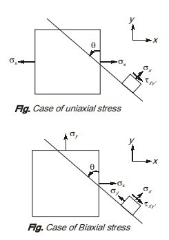 Biaxial Stress
Alt: Biaxial stress diagram illustrating stress components in two perpendicular directions.
8.7. Applications
Biaxial stress analysis is widely used in:
- Pressure Vessel Design: Designing safe and efficient pressure vessels.
- Aircraft Structures: Analyzing stresses in aircraft fuselages and wings.
- Automotive Engineering: Assessing stresses in car bodies and chassis.
8.8. Example
Consider a thin-walled cylindrical pressure vessel with an internal pressure ( p ), radius ( r ), and wall thickness ( t ). The hoop stress ( sigma_h ) and longitudinal stress ( sigma_l ) are:
$$
sigma_h = frac{pr}{t}
$$
$$
sigma_l = frac{pr}{2t}
$$
These stresses are biaxial, and the maximum shear stress is:
$$
tau_{text{max}} = frac{sigma_h – sigma_l}{2} = frac{frac{pr}{t} – frac{pr}{2t}}{2} = frac{pr}{4t}
$$
8.9. Practical Implications for Uniforms at onlineuniforms.net
Understanding biaxial stress is crucial for onlineuniforms.net in designing uniforms that can withstand complex stress conditions:
- Reinforced Seams: Ensuring seams are reinforced to handle stresses from multiple directions.
- Durable Materials: Selecting materials that maintain integrity under biaxial stress, such as in high-movement areas like elbows and knees.
- Comfort and Flexibility: Balancing durability with comfort by strategically using materials that can stretch and flex without failing under biaxial stress.
9. How Do You Design a Beam For Strength?
Designing a beam for strength involves a systematic approach, starting with understanding the applied loads, selecting appropriate materials, and calculating the required section modulus, all to ensure the beam can safely withstand the expected stresses. onlineuniforms.net considers these principles when selecting durable materials for long-lasting uniforms.
9.1. Steps for Designing a Beam for Strength
-
Determine the Applied Loads:
- Identify all the loads acting on the beam, including dead loads (self-weight), live loads (occupancy, equipment), and environmental loads (wind, snow).
- Calculate the magnitude and distribution of these loads along the beam’s length.
-
Calculate the Shear Force and Bending Moment:
- Draw shear force and bending moment diagrams to determine the maximum shear force (Vmax) and maximum bending moment (Mmax) acting on the beam.
-
Select a Suitable Material:
- Choose a material with adequate strength and stiffness for the application. Common materials include steel, timber, and reinforced concrete.
- Determine the allowable bending stress ((sigma{allowable})) and allowable shear stress ((tau{allowable})) for the selected material.
-
Calculate the Required Section Modulus:
- Use the flexure formula to calculate the required section modulus (S) based on the maximum bending moment:
$$
S = frac{M{max}}{sigma{allowable}}
$$
- Use the flexure formula to calculate the required section modulus (S) based on the maximum bending moment:
-
Select a Beam Section:
- Choose a beam section from standard tables or catalogs that provides a section modulus equal to or greater than the required section modulus.
- Consider factors such as beam depth, width, and weight when selecting the section.
-
Check for Shear Strength:
- Verify that the selected beam section can resist the maximum shear force:
$$
tau{max} = frac{V{max}Q}{Ib} leq tau_{allowable}
$$
Where:- (Q) is the first moment of area of the section above or below the point where shear stress is being calculated.
- (I) is the moment of inertia of the section.
- (b) is the width of the section at the point where shear stress is being calculated.
- For rectangular beams, the maximum shear stress is:
$$
tau{max} = frac{3V{max}}{2A}
$$
Where (A) is the cross-sectional area of the beam.
- Verify that the selected beam section can resist the maximum shear force:
-
Check for Deflection:
- Calculate the maximum deflection of the beam under the applied loads.
- Ensure that the deflection is within acceptable limits, typically specified as a fraction of the beam’s span (e.g., L/360).
-
Consider Other Factors:
- Check for buckling, lateral-torsional buckling, and other potential failure modes.
- Account for any special loading conditions or environmental factors that may affect the beam’s performance.
9.2. Material Selection
Choosing the right material is critical for beam design:
- Steel: High strength, high stiffness, but susceptible to corrosion.
- Timber: Lightweight, renewable, but lower strength and stiffness compared to steel.
- Reinforced Concrete: High compressive strength, durable, but heavy and requires formwork.
9.3. Example Calculation
Consider a simply supported beam with a span of 6 meters, subjected to a uniformly distributed load of 10 kN/m.
- Applied Loads: Uniformly distributed load (w = 10 text{ kN/m}).
- Shear Force and Bending Moment:
- Maximum bending moment (M_{max} = frac{wL^2}{8} = frac{10 times 6^2}{8} = 45 text{ kNm}).
- Maximum shear force (V_{max} = frac{wL}{2} = frac{10 times 6}{2} = 30 text{ kN}).
- Material Selection: Assume steel with (sigma_{allowable} = 160 text{ MPa}).
- Required Section Modulus:
- (S = frac{M{max}}{sigma{allowable}} = frac{45 times 10^6}{160} = 281.25 times 10^3 text{ mm}^3).
- Beam Section Selection: Choose a standard steel section with (S geq 281.25 times 10^3 text{ mm}^3).
- Shear Strength Check: Verify that the selected section can resist the maximum shear force.
- Deflection Check: Ensure that the deflection is within acceptable limits.
9.4. Practical Considerations
- Safety Factors: Apply appropriate safety factors to account for uncertainties in loading and material properties.
- Code Compliance: Ensure that the design complies with relevant building codes and standards.
- Cost Optimization: Consider the cost of materials, fabrication, and installation when selecting a beam section.
9.5. How onlineuniforms.net Applies These Principles
onlineuniforms.net applies these principles by:
- Material Testing: Rigorously testing fabrics for strength and durability.
- Design Innovation: Implementing innovative designs that distribute stress effectively.
- Quality Control: Maintaining strict quality control to ensure uniforms meet performance requirements.
10. What Are Some Common FAQs About Beams Of Uniform Strength?
Here are some frequently asked questions (FAQs) about beams of uniform strength, covering essential aspects from definition to practical applications, all aimed at providing clear and helpful information.
10.1. What Exactly Is a Beam of Uniform Strength?
A beam of uniform strength is a beam designed